GLOBAL
How to Prevent Liquid Cooling Hose Leakage in AI Data Center Systems
In a liquid-cooled AI data center, a hose leak is more than a maintenance issue.
Coolant connections can be located close to servers, cold plates, manifolds, CDUs and other sensitive equipment. A small leak can therefore create an operational problem if it is not detected and addressed quickly.
Leak prevention begins well before the hose is installed. Material selection, hose construction, connection design, routing, installation and validation all have a role to play.
For a broader discussion of hose reliability, see How Pressure and Temperature Affect Liquid Cooling Hose Reliability in AI Data Centers.
1. Why Leakage Is a Serious Concern in AI Data Centers
Liquid cooling brings coolant directly to heat-generating components. This creates a more direct thermal path than traditional air cooling, but it also introduces fluid connections into the server environment.
Depending on the cooling architecture, flexible hoses may connect cold plates, manifolds, distribution units and quick-disconnect components.
Leak prevention is therefore part of overall cooling-system reliability.
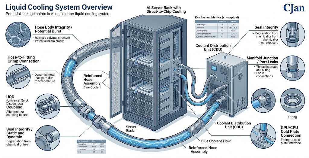
2. Where Can a Liquid Cooling System Leak?
A leak does not necessarily originate from the hose tube itself.
Potential leak locations include:
- Hose body
- Hose-to-fitting connection
- Fitting connection
- Seal or O-ring
- UQD connection
- Manifold interface
- Cold plate connection
3. Start With the Correct Hose Material
Material selection is the first step in preventing long-term hose problems.
The hose inner layer must be appropriate for the coolant being used and the intended temperature range.
Material compatibility should not be determined from temperature resistance alone.
As discussed in How Coolant Compatibility Affects Liquid Cooling Hose Selection for AI Data Centers, the actual coolant formulation and exposure conditions should be considered.
4. Confirm the Operating Pressure
Every liquid cooling hose should be selected according to the actual pressure requirements of the application.
Normal operating pressure, maximum pressure and possible pressure fluctuations should all be considered.
Repeated pressure cycling can place additional stress on the hose and connections.
5. Temperature Also Matters
Temperature affects both hose materials and the coolant itself.
The hose should be appropriate for the normal operating temperature as well as the expected maximum condition.
Thermal cycling should also be considered where the cooling system experiences repeated temperature changes.
Pressure and temperature should be evaluated together rather than as isolated specifications.
6. Use the Correct Hose Construction
A liquid cooling hose can contain several functional layers.
The inner layer handles coolant contact, while reinforcement helps provide mechanical strength and the outer layer provides environmental protection.
The construction should match the pressure, temperature and mechanical requirements of the intended system.
7. Select the Correct Hose Diameter
Hose diameter is normally selected according to required flow and hydraulic performance.
An unsuitable hose diameter can increase pressure loss and may affect system operation.
For a detailed discussion of sizing, see How to Select the Right Liquid Cooling Hose Size for AI Data Centers.
8. Pay Attention to the Hose-to-Fitting Connection
The connection between the flexible hose and fitting is one of the most important areas of the assembly.
The connection method should be appropriate for the hose construction, fitting design and application requirements.
A hose with suitable pressure capability can still experience leakage if the connection is improperly assembled.
9. UQD Connections Need Careful Installation
UQDs provide a practical way to disconnect cooling components during maintenance.
However, every disconnectable connection introduces an interface that needs to be properly installed and maintained.
The UQD should be compatible with the hose assembly and the coolant, and the connection should be made according to the applicable manufacturer's instructions.
10. Do Not Force a Hose Into Position
Installation geometry can have a direct effect on hose reliability.
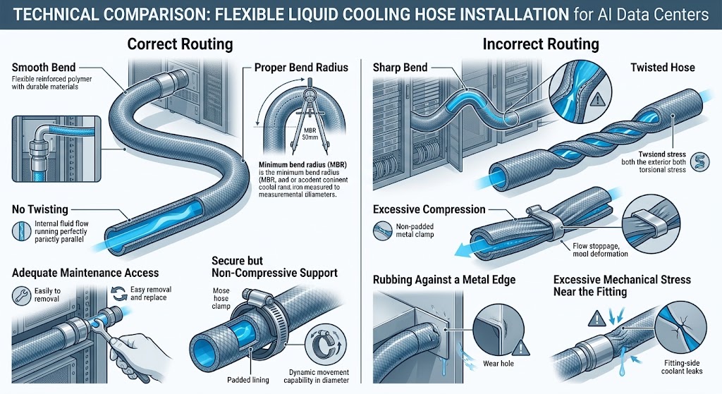
A hose should not be twisted or forced into an excessively tight bend simply to reach a connection.
Forced routing can create unnecessary mechanical stress at the hose body or connection area.
11. Respect the Required Bend Radius
Flexible hoses are designed to bend, but each construction has limits.
Excessive bending can deform the hose and increase stress within the assembly.
During installation, the hose should maintain an appropriate bend radius and should not be sharply folded.
12. Avoid Twisting the Hose
Bending and twisting are not the same movement.
A hose can sometimes be routed through a bend while remaining in a neutral orientation. Twisting the hose around its own axis can introduce additional mechanical stress.
Where possible, the installation should allow the hose to follow a natural path without torsional loading.
13. Prevent External Damage
Hoses can also be damaged by the surrounding installation environment.
Potential sources include:
- Sharp metal edges
- Repeated rubbing
- Clamping at unsuitable locations
- Excessive vibration
- Contact with hot surfaces
- Improper routing around moving components
The outer protective layer should not be treated as a substitute for proper routing and protection.
14. Avoid Excessive Vibration
Cooling equipment can generate mechanical vibration through pumps, fans, valves and other components.
Flexible hoses can help isolate movement, but they still need to be routed appropriately.
Where vibration is significant, the hose assembly should be evaluated for the expected mechanical conditions.
15. Control Hose Movement
A hose that moves freely may rub against nearby components or repeatedly bend at the same location.
Suitable supports or routing features can help maintain the intended hose geometry.
However, supports should not compress or deform the hose unnecessarily.
16. Check the Connection Before System Startup
Visual inspection should be performed before introducing coolant into the system.
Check that:
- Connections are fully engaged.
- Hoses are routed correctly.
- No sharp bends are present.
- No visible damage exists.
- UQDs are properly connected.
- Fittings are correctly installed.
17. Pressure Testing Before Operation
Where required by the system design, pressure testing can help identify problems before the cooling system is placed into normal service.
The test pressure and procedure should follow the applicable hose, assembly and system specifications.
18. Leak Testing Is Different From Visual Inspection
A visual inspection can identify obvious installation problems, but it cannot detect every possible leakage path.
Depending on the system requirements, additional leak-testing methods may be appropriate.
The testing method should be selected according to the cooling architecture and required leak performance.
19. Do Not Ignore Small Signs of Leakage
A small amount of moisture, residue or an unexpected change in coolant level should not automatically be dismissed.
Any indication of leakage should be investigated to determine its source.
The cause may be a connection issue, seal problem, hose damage or another component in the cooling loop.
20. Inspect the Complete Assembly, Not Only the Hose
A hose may remain visually intact while a connection develops a problem.
For this reason, inspection should cover the complete fluid path.
| Component | Inspection Focus |
|---|---|
| Hose | Damage, deformation, wear |
| Fitting | Connection integrity |
| Seal | Condition and compatibility |
| UQD | Engagement and sealing |
| Manifold | Interface condition |
| Cold Plate | Connection integrity |
21. Maintenance Access Should Be Considered During Design
Liquid cooling components may need to be disconnected during server maintenance or replacement.
Hose routing should provide enough access for technicians to inspect and service the connection without putting unnecessary stress on the hose.
A hose that is difficult to access may be more likely to be incorrectly handled during maintenance.
22. Avoid Repeatedly Reusing Components Without Evaluation
Some liquid cooling assemblies are designed for repeated connection and disconnection, while others are intended for a different service pattern.
Reuse requirements should therefore be defined during system design.
UQD manufacturers' connection-cycle specifications and hose assembly requirements should be followed where applicable.
23. Cleanliness Can Affect Connection Reliability
Liquid cooling systems can have specific cleanliness requirements.
Contamination around fittings, seals or disconnect interfaces can interfere with proper sealing or introduce unwanted material into the coolant loop.
Assembly and maintenance procedures should therefore address cleanliness requirements appropriate to the cooling system.
24. Monitor Pressure and Temperature During Operation
Monitoring operating conditions can help identify changes before they become larger problems.
Useful system parameters may include:
- Coolant pressure
- Coolant temperature
- Flow rate
- Coolant level
- Leak detection signals
The exact monitoring strategy depends on the cooling system architecture.
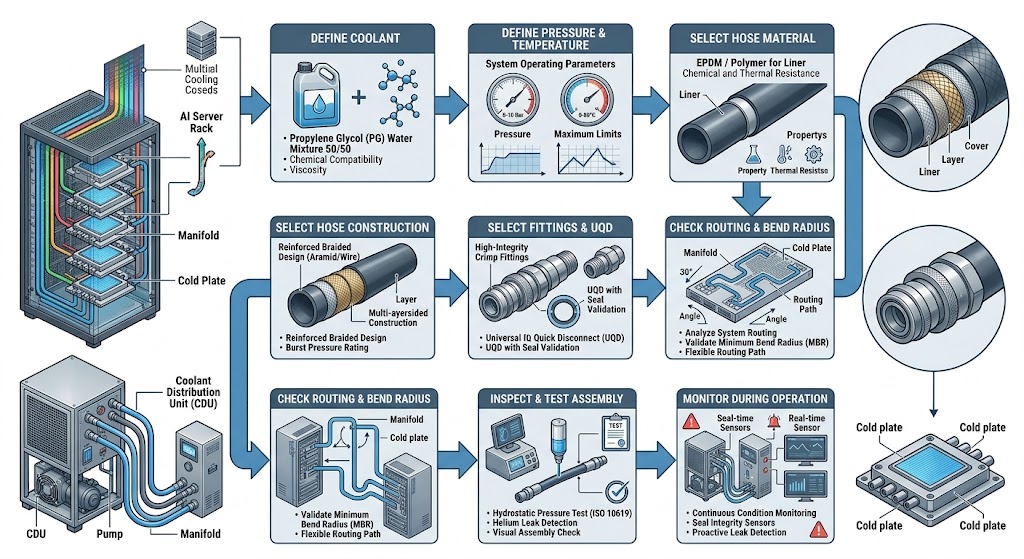
25. A Practical Leak-Prevention Workflow
This approach moves leak prevention from a reactive maintenance task to an engineering process.
26. Five Common Causes of Liquid Cooling Hose Leakage
1. Incorrect Material Selection
The hose material may not be suitable for the actual coolant or temperature range.
2. Poor Connection Assembly
An improperly installed hose-to-fitting or UQD connection can create a leakage path.
3. Excessive Bending or Twisting
Incorrect routing can create unnecessary mechanical stress.
4. External Damage
Rubbing, sharp edges or excessive vibration can damage the hose over time.
5. Insufficient Validation
Installation or assembly problems may remain undiscovered if the system is not appropriately inspected or tested before operation.
27. How Hose Reliability and Leak Prevention Work Together
Leak prevention should not be treated as a separate topic from hose reliability.
Pressure, temperature, coolant compatibility and mechanical routing all influence long-term performance.
The previous article in this series, How Pressure and Temperature Affect Liquid Cooling Hose Reliability in AI Data Centers, covers these operating conditions in greater detail.
28. CJAN Liquid Cooling Hose Options
CJAN provides liquid cooling hose configurations that can be evaluated according to coolant, pressure, temperature, flow, flexibility and connection requirements.
The current CJAN LCH Liquid Cooling Hose is part of the liquid cooling product range.
Other configurations include LCH-SD and LCH-SDS.
For AI data center applications, the appropriate configuration should be selected according to the actual coolant, pressure, temperature, flow rate, installation space and connection requirements.
29. A Simple Pre-Deployment Checklist
| Check | Status |
|---|---|
| Coolant compatibility confirmed | Required |
| Pressure requirements confirmed | Required |
| Temperature requirements confirmed | Required |
| Hose size confirmed | Required |
| Fittings selected | Required |
| UQD compatibility confirmed | If applicable |
| Bend radius checked | Required |
| Routing checked | Required |
| Assembly inspected | Required |
| Leak / pressure testing completed | According to system requirements |
Conclusion
Preventing liquid cooling hose leakage in an AI data center starts with proper engineering rather than waiting for a leak to occur.
The coolant, pressure, temperature and hose material should be defined first. Hose construction, diameter, fittings, UQDs and routing should then be selected around the actual system requirements.
Installation quality is equally important. Sharp bends, twisting, excessive vibration, external abrasion and poorly assembled connections can undermine an otherwise suitable hose.
Before deployment, appropriate inspection and testing can provide an additional layer of confidence.
CJAN's LCH, LCH-SD and LCH-SDS configurations can be evaluated for liquid cooling applications according to specific operating and connection requirements.
For more information, visit the CJAN Liquid Cooling Solutions page or review the CJAN LCH Liquid Cooling Hose.