GLOBAL
Liquid Cooling Hose Assembly Testing: Pressure, Leak and Performance Checks
A liquid cooling hose assembly may contain only a few components, but its reliability depends on how those components work together.
In an AI data center, a typical assembly can include a flexible hose, fittings, sealing components and UQD connections. Once installed, the assembly becomes part of a continuous coolant circuit serving GPUs, cold plates, manifolds or other thermal-management equipment.
For this reason, testing should not stop at checking the hose itself. The completed assembly needs to be evaluated according to the pressure, leakage, flow and mechanical requirements of the intended application.
1. Why Test a Liquid Cooling Hose Assembly?
A hose can meet its individual material and pressure specifications while the completed assembly still contains a connection problem.
For example, a potential failure may originate from:
- Incorrect fitting installation
- Improper hose insertion
- Incorrect crimping
- Damaged sealing components
- Incorrect UQD engagement
- Excessive hose bending
- Assembly contamination
These conditions may not be identified by inspecting the hose alone.
Testing the complete assembly provides an additional verification step before installation.
2. What Is a Liquid Cooling Hose Assembly?
A liquid cooling hose assembly is more than a length of hose.
Depending on the application, an assembly may contain:
- Flexible liquid cooling hose
- End fittings
- UQD connections
- Sealing elements
- Crimped or mechanically secured interfaces
The actual construction depends on the cooling architecture and connection requirements.
CJAN's liquid cooling application range provides hose solutions intended for thermal-management applications:
3. Testing Should Start With the Application Requirements
Before defining a test procedure, engineers should understand the conditions the assembly will experience in service.
Important parameters may include:
- Working pressure
- Required flow rate
- Coolant type
- Operating temperature
- Connection type
- Expected service conditions
- Installation configuration
Test conditions should be related to the actual application rather than selected arbitrarily.
4. Pressure Testing
Pressure testing is commonly used to evaluate the pressure integrity of a completed hose assembly.
A simplified test arrangement can be represented as:
The assembly is subjected to a defined test condition and monitored for evidence of pressure loss, leakage or abnormal deformation.
The actual pressure, duration and acceptance criteria should be established according to the applicable product specification, customer requirement or test standard.
5. Working Pressure Is Not the Same as Test Pressure
One important distinction is the difference between normal working pressure and a test pressure.
Working pressure describes the intended operating condition of the assembly.
A test pressure may be defined separately for validation purposes.
For additional information about pressure selection, see Liquid Cooling Hose Pressure Rating: How Much Pressure Does an AI Data Center Hose Need?.
6. Pressure Integrity Testing
Pressure integrity testing focuses on whether the completed assembly can maintain the specified pressure without unacceptable leakage or structural problems.
Areas of interest include:
- Hose body
- Fitting connections
- Crimped areas
- Sealing interfaces
- UQD connections
The assembly should be inspected for visible leakage, abnormal deformation or other evidence of failure.
7. Leak Testing
Leak testing has a different emphasis from general pressure testing.
The objective is to determine whether the assembly has an unacceptable fluid or gas leakage path under the defined test conditions.
Depending on the application, leak testing may be performed using an appropriate test medium and measurement method.
The selected method should be suitable for the assembly design and the required sensitivity.
8. Why Visual Inspection Alone Is Not Enough
A visual inspection can identify obvious problems, but it cannot verify every aspect of connection integrity.
For example, a connection may appear correctly assembled while containing:
- An incorrectly positioned seal
- Insufficient insertion depth
- Improper crimp dimensions
- Internal damage
- A small leakage path
This is why visual inspection is generally most useful as one part of a broader verification process.
9. Inspect the Hose Before Testing
Before applying pressure or another test condition, the assembly should be visually checked.
Inspect for:
- Cuts or abrasions
- Crushing
- Abnormal deformation
- Contamination
- Incorrect fitting orientation
- Damaged connection components
Any obvious assembly defect should be addressed before proceeding to subsequent testing.
10. Inspect Fitting Installation
Fitting installation should be checked against the assembly specification.
Depending on the connection method, this may include:
- Insertion depth
- Fitting orientation
- Crimp dimensions
- Clamp position
- Torque where applicable
- Visible damage
Controlled assembly procedures help reduce variation between individual hose assemblies.
11. Check UQD Engagement
Where a UQD is incorporated into the assembly, the connection should be checked for correct mating and locking.
Important checks can include:
- Correct mating components
- Full engagement
- Locking mechanism position
- Seal condition
- Absence of visible damage
The exact inspection procedure should follow the coupling manufacturer's requirements.
For background on UQD selection, see UQD vs. Traditional Quick Disconnects for AI Data Center Cooling.
12. Check Flow Performance
A hose assembly can be leak-free and still introduce excessive hydraulic resistance.
For this reason, performance validation may also include flow-related measurements.
Each component contributes to the hydraulic characteristics of the cooling loop.
Where required, engineers should verify that the completed assembly does not introduce unacceptable pressure loss at the intended flow rate.
See Liquid Cooling Hose Pressure Drop: How to Calculate and Control It in AI Data Centers.
13. Pressure Drop Testing
Pressure drop can be evaluated by measuring the pressure difference across the hose assembly at a defined flow rate.
The measured result can then be compared with the expected hydraulic performance.
This can be particularly useful when the assembly contains multiple fittings or UQD connections.
14. Why Flow Testing Matters for AI Cooling
AI server cooling systems depend on controlled coolant circulation.
If an assembly introduces excessive resistance, the cooling system may require additional pump pressure to achieve the target flow.
For this reason, hose assembly validation can extend beyond simple leak prevention.
It can also help confirm that the assembly is appropriate for the intended hydraulic design.
15. Temperature Considerations During Testing
Testing at room temperature may not reproduce every condition experienced during operation.
Where application requirements call for it, engineers may need to consider temperature effects on:
- Hose materials
- Seals
- Fittings
- UQD components
- Assembly dimensions
Temperature-dependent testing should be defined according to the actual application requirements.
16. Pressure and Temperature Should Be Considered Together
Pressure capability can vary with temperature.
Therefore, a pressure test conducted at one temperature should not automatically be interpreted as proof of performance under every operating condition.
Engineers should use the manufacturer's pressure-temperature limits when defining operating and validation conditions.
See How Pressure and Temperature Affect Liquid Cooling Hose Reliability in AI Data Centers.
17. Coolant Compatibility Testing
The selected test medium should also be considered carefully.
A hose assembly intended for a specific coolant should ultimately be evaluated with materials and conditions that represent the intended application where required.
This is particularly relevant when the assembly contains multiple wetted materials.
The compatibility chain includes:
All wetted components should be considered together.
18. Test the Connection Interfaces
Connection interfaces deserve particular attention because they combine several materials and mechanical components.
A typical interface may contain:
- Flexible hose
- Rigid fitting
- Seal
- Locking mechanism
- UQD body
The interface should be tested in its assembled configuration rather than assuming that individual component specifications guarantee assembly performance.
19. Mechanical Loading During Testing
Where the application involves bending or movement, testing only a perfectly straight hose may not represent the installed condition.
Engineers may need to consider the effects of:
- Bending
- Hose routing
- Equipment movement
- Vibration
- Connection orientation
The appropriate test configuration depends on the actual application.
See Liquid Cooling Hose Bend Radius: Why Flexibility Matters in AI Server Racks.
20. Test the Assembly After Routing
Routing can change the mechanical loading experienced by a hose assembly.
For critical installations, it can therefore be useful to consider the assembled routing condition rather than testing only a straight, unloaded assembly.
The appropriate sequence depends on the assembly process and customer requirements.
21. Common Testing Methods
| Test / Check | Primary Purpose |
|---|---|
| Visual inspection | Identify visible assembly defects |
| Pressure testing | Verify pressure integrity under defined conditions |
| Leak testing | Identify unacceptable leakage |
| Flow testing | Verify hydraulic performance |
| Pressure-drop measurement | Evaluate hydraulic resistance |
| Dimensional inspection | Verify assembly dimensions |
| Connection inspection | Verify fitting and UQD engagement |
22. Pressure Testing Does Not Replace Leak Testing
These two tests are related but should not automatically be treated as identical.
Pressure testing evaluates the assembly under a defined pressure condition.
Leak testing focuses on identifying an unacceptable leakage path using a defined detection method.
The appropriate test combination depends on the required performance level of the application.
23. Define Acceptance Criteria Before Testing
A test is difficult to interpret if the acceptance criteria are not defined in advance.
An engineering test specification should identify, where applicable:
- Test medium
- Test pressure
- Test temperature
- Test duration
- Flow rate
- Allowable leakage
- Pressure-drop limits
- Visual acceptance criteria
24. Record Test Results
Test records can provide useful traceability for hose assemblies used in critical applications.
A test record may include:
- Assembly identification
- Hose model
- Fitting configuration
- UQD configuration
- Test date
- Test conditions
- Measured pressure
- Measured flow
- Leak-test result
- Final inspection result
25. Traceability Can Help During Maintenance
For large data center deployments, many similar hose assemblies may be installed in the same facility.
Clear identification can help maintenance teams determine which assembly was tested and what configuration was used.
This becomes particularly useful when assemblies have different lengths, fittings or connection configurations.
26. What Happens If an Assembly Fails Testing?
A failed test should trigger an investigation rather than simply replacing the assembly without understanding the cause.
Potential causes may include:
- Incorrect assembly
- Incorrect component selection
- Damaged seal
- Improper fitting installation
- Incorrect UQD engagement
- Hose damage
- Test setup error
The failed assembly should be evaluated according to the applicable quality procedure.
27. Retesting After Corrective Action
If a problem is identified and corrected, the assembly should be retested according to the applicable procedure.
Simply correcting the visible problem without verifying the complete assembly may leave other issues undetected.
28. Testing New Hose Assemblies
Newly manufactured assemblies should be validated according to the applicable quality and product requirements.
The exact testing level depends on:
- Product design
- Customer specification
- Application criticality
- Manufacturing process
- Applicable standards
Not every assembly requires the same test program.
29. Testing After Field Installation
Factory testing does not necessarily eliminate the need for installation checks.
During field installation, hoses can be:
- Bent
- Rotated
- Moved
- Connected to different equipment
- Exposed to installation loads
Final system commissioning should therefore include the appropriate verification steps for the installed configuration.
30. Testing After Maintenance
When a liquid cooling circuit is opened during maintenance, the affected connections should be checked before the system is returned to normal operation.
This is especially important for connections that have been disconnected and reconnected.
Inspection and testing requirements should follow the facility's maintenance procedures.
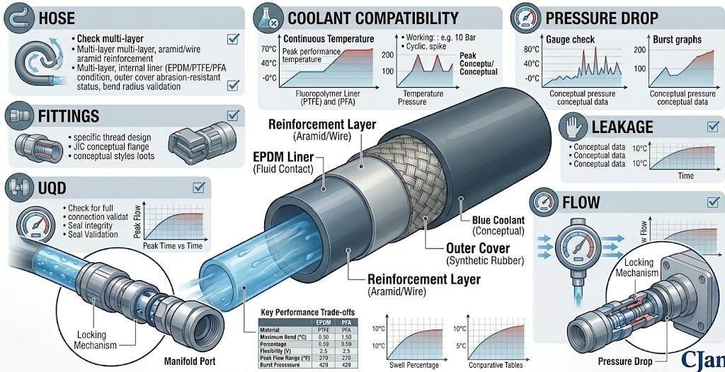
31. A Practical Liquid Cooling Hose Assembly Test Sequence
32. Testing and Liquid Cooling System Reliability
Testing cannot eliminate every possible failure mode, but it can identify defects before an assembly enters service.
This is especially useful in AI data center applications where cooling availability is closely linked to equipment operation.
A practical reliability strategy therefore combines:
- Correct hose selection
- Correct fitting selection
- Correct UQD selection
- Controlled assembly
- Appropriate testing
- Installation inspection
- Ongoing maintenance
33. CJAN Liquid Cooling Hose Assemblies
CJAN provides liquid cooling hose solutions that can be incorporated into engineered hose assemblies for AI data center and other thermal-management applications.
Relevant products include:
For an engineered assembly, the hose should be matched with the appropriate fitting and UQD according to the required coolant, pressure, temperature, flow and installation conditions.
See the CJAN Liquid Cooling application page for additional information.
34. A Practical Testing Checklist
| Item | Verification |
|---|---|
| Hose | Correct model and construction |
| Fittings | Correct type and installation |
| UQD | Correct mating and engagement |
| Coolant | Compatible with wetted materials |
| Pressure | Defined test condition |
| Leakage | Within specified acceptance criteria |
| Flow | Within required performance range |
| Pressure drop | Within system design limits |
| Appearance | No visible assembly defects |
| Records | Results documented for traceability |
Conclusion
Testing a liquid cooling hose assembly is more than checking whether a hose can withstand pressure.
The completed assembly should be evaluated according to the conditions it will experience in the cooling system, including pressure, leakage, flow, temperature and mechanical loading.
Pressure testing can help verify pressure integrity. Leak testing can identify unacceptable leakage paths. Flow and pressure-drop checks can help confirm hydraulic performance. Visual and dimensional inspections can identify assembly defects.
For AI data center liquid cooling applications, this approach helps connect hose selection with the practical requirements of installation, commissioning and long-term maintenance.
Learn more about CJAN liquid cooling hose solutions and related engineering applications.