GLOBAL
How to Design Reliable Liquid Cooling Hose Assemblies for AI Servers
In an AI server cooling system, the hose itself is only one part of the connection.
A complete liquid cooling hose assembly may include the hose, fittings, seals, quick disconnects and other connection components. The way these parts are selected and assembled can directly affect the reliability of the cooling circuit.
This becomes particularly important in high-density AI servers, where coolant must be delivered continuously to high-power processors and returned to the cooling distribution system without unnecessary pressure loss or leakage risk.
For this reason, hose material, reinforcement, diameter, fittings, routing, operating conditions and assembly quality should be considered together.
1. What Is a Liquid Cooling Hose Assembly?
A liquid cooling hose assembly is a finished flexible fluid connection consisting of a hose and the components required to connect it to the cooling system.
A simplified assembly can be represented as:
Depending on the system design, the assembly may also incorporate UQD couplings, clamps, crimped fittings, seals or other connection components.
The final assembly should be treated as one engineered component because the hose and its connections work together during operation.
2. Why Hose Assembly Design Matters in AI Servers
AI servers can generate substantial heat loads within a relatively compact physical space.
Liquid cooling allows heat to be transferred away from high-power components through a controlled coolant circuit.
The flexible hose assemblies used within this circuit need to maintain fluid containment while accommodating equipment layout, installation constraints and service requirements.
Typical requirements include:
- Suitable coolant compatibility
- Appropriate pressure capability
- Suitable temperature capability
- Required coolant flow
- Controlled pressure loss
- Reliable connections
- Appropriate bend radius
- Mechanical durability
A hose assembly that satisfies only one of these requirements may still be unsuitable for the complete cooling system.
3. Start With the Cooling System Requirements
The hose assembly should be specified after the basic operating conditions have been established.
Engineers should first determine:
- Coolant type
- Coolant concentration, where applicable
- Required flow rate
- Operating pressure
- Maximum pressure
- Operating temperature
- Maximum temperature
- Available installation space
- Required hose length
- Connection type
These parameters provide the basis for selecting the hose construction and connection components.
For a broader selection process, see How to Select the Right Liquid Cooling Hose for AI Data Centers.
4. Select the Hose Material for the Coolant
The fluid-contact material is one of the first decisions in hose selection.
Different coolant formulations can interact differently with polymer materials, seals and other wetted components.
Potential hose materials for liquid cooling applications include EPDM, silicone, PTFE, PFA and other engineered constructions.
The correct choice depends on the actual coolant chemistry and operating conditions rather than on the material name alone.
For example, a hose suitable for one water-glycol formulation should not automatically be assumed to be suitable for another coolant without compatibility verification.
See How Coolant Compatibility Affects Liquid Cooling Hose Selection for AI Data Centers.
5. Select the Appropriate Hose Construction
The hose construction should match the mechanical requirements of the application.
A basic flexible hose may use a single-layer construction, while applications requiring additional mechanical support may use reinforced construction.
A typical reinforced hose can include:
The reinforcement can contribute to pressure capability, dimensional stability and mechanical durability.
However, reinforcement should not be selected independently from the hose diameter, bend radius and operating pressure.
See How Hose Reinforcement Affects Liquid Cooling System Performance.
6. Select the Correct Hose Diameter
Hose internal diameter is closely related to coolant flow and pressure loss.
If the hose is too small for the required flow rate, pressure loss can increase and the cooling circuit may require more pumping energy.
If the hose is unnecessarily large, installation space and connection dimensions may become more difficult to manage.
The target should therefore be an appropriate balance between hydraulic performance and physical integration.
See How to Select the Right Liquid Cooling Hose Size for AI Data Centers.
7. Consider Pressure and Temperature Together
Pressure and temperature should not be evaluated independently.
Material properties can change with temperature, while the allowable operating conditions of a hose assembly can depend on both pressure and temperature.
When specifying an assembly, engineers should identify:
- Normal operating pressure
- Maximum operating pressure
- Normal operating temperature
- Maximum temperature
- Pressure cycling
- Temperature cycling
The final hose and fitting combination should be rated for the actual operating envelope.
See How Pressure and Temperature Affect Liquid Cooling Hose Reliability in AI Data Centers.
8. Choose the Right Fitting Type
The fitting is the transition point between the flexible hose and the rest of the cooling system.
Connection types may include threaded fittings, barbed connections, crimped assemblies and quick-disconnect solutions depending on the system architecture.
The selection should consider:
- Connection standard
- Hose dimensions
- Pressure rating
- Sealing method
- Coolant compatibility
- Installation space
- Maintenance requirements
The fitting should be compatible with the hose construction and the equipment-side connection.
See Liquid Cooling Hose Fittings: How to Select the Right Connection Type.
9. UQD Connections for AI Server Cooling
UQD connections can be useful where cooling equipment needs to be disconnected during installation, service or replacement.
When using UQD couplings, the coupling should be considered together with the hose and fitting assembly.
Important considerations include:
- Flow requirements
- Pressure capability
- Temperature
- Coolant compatibility
- Connection size
- Sealing performance
- Service requirements
UQD should not be treated simply as a convenience component. Its connection characteristics can affect the overall assembly design.
See Liquid Cooling Hose Quick Disconnects: How to Choose UQD Couplings for AI Servers.
10. Hose Length and Pressure Drop
Hose length has a direct relationship with hydraulic resistance.
As hose length increases, frictional pressure loss generally increases for a given internal diameter, coolant and flow condition.
This means hose routing should not be designed solely around physical convenience.
Engineers should also consider whether excessive hose length creates unnecessary pressure loss.
For detailed pressure-drop considerations, see Liquid Cooling Hose Pressure Drop: How to Calculate and Control It in AI Data Centers.
11. Hose Routing and Bend Radius
Even a correctly specified hose assembly can perform poorly if it is routed incorrectly.
The hose should be installed without excessive bending, twisting, compression or sharp directional changes.
The minimum bend radius specified for the hose should be respected during installation.
Good routing should provide enough space for the hose to follow a natural path while avoiding unnecessary loops and mechanical stress.
See Liquid Cooling Hose Bend Radius: Why Flexibility Matters in AI Server Racks.
12. Avoid Twisting the Hose During Installation
Twisting is different from normal bending.
A hose can appear correctly positioned while carrying torsional stress if the fittings are installed with the hose rotated from its natural orientation.
Repeated movement or pressure cycling can make this condition more significant.
During assembly, the hose should be positioned so that the intended bending direction does not introduce unnecessary torsion.
13. Keep Fitting Loads Under Control
Hose fittings should not be used to compensate for poor alignment between components.
If two connection points are misaligned, forcing the hose into position can create additional mechanical loads on the fittings.
A better approach is to adjust the routing or connection geometry so that the hose can connect naturally.
This is particularly important for rack-level cooling systems where multiple connections may be installed within a restricted space.
14. Consider Thermal Expansion
Cooling equipment, racks and piping structures can experience dimensional changes as operating temperatures change.
The hose assembly can provide flexibility between components, but it should have sufficient available movement without being stretched, compressed or bent beyond its design limits.
Where temperature changes are significant, the expected movement should be considered during hose length and routing design.
15. Design for Maintenance Access
AI server cooling systems require practical service access.
A hose assembly should therefore be designed not only for normal operation but also for maintenance.
Engineers should consider whether technicians can:
- Access the fittings
- Operate UQD connections where applicable
- Inspect hose surfaces
- Identify potential leakage
- Remove the assembly without disturbing adjacent components
A connection that is technically functional but difficult to service can increase maintenance complexity.
16. Minimize Unnecessary Hose Length
Longer is not necessarily better.
Additional hose length can increase material usage, occupy more installation space and contribute to additional pressure loss.
At the same time, the hose should not be so short that it becomes difficult to install or creates excessive mechanical tension.
The correct length is therefore the length that provides sufficient routing flexibility without unnecessary slack.
17. Avoid Sharp Bends Near Fittings
The area immediately next to a fitting is an important part of the assembly.
Forcing a hose into a sharp bend directly at the fitting can create concentrated mechanical stress.
Where possible, the hose should have sufficient straight length or controlled routing near the connection.
This also makes installation and inspection easier.
18. Check the Complete Coolant Flow Path
A hose assembly should be evaluated as part of the complete flow path.
Each hose section contributes to the total hydraulic resistance of the cooling circuit.
Fittings, couplings, bends and changes in internal diameter can also contribute to pressure loss.
For this reason, engineers should consider the entire circuit rather than evaluating each hose in isolation.
19. Consider the Connection Between Hose and Cold Plate
At the server level, the hose assembly may connect directly or indirectly to a cold plate or distribution manifold.
The connection should provide sufficient sealing performance while accommodating the available installation space.
The hose should not introduce unnecessary loads into the cold plate connection.
Where the cold plate is installed within a dense server environment, connection orientation can also affect cable management, airflow clearance and service access.
20. Design CDU-to-Rack Hose Assemblies Carefully
CDU-to-rack connections can involve relatively long flexible connections compared with connections located directly inside a server.
These assemblies may need to accommodate:
- Rack movement
- Installation tolerances
- Maintenance access
- Pressure requirements
- Required flow
- Available routing space
The hose should have enough length for installation and service without creating excessive loops.
See CDU to Rack Connections: Designing Reliable Liquid Cooling Hose Assemblies for AI Data Centers.
21. Assembly Method Matters
The way the hose is connected to its fittings is part of the assembly design.
Depending on the product and connection system, assembly may involve crimping, clamping or other controlled joining methods.
The connection process should follow the manufacturer's specified procedure.
An appropriately selected hose can still experience leakage or premature failure if the assembly process is inconsistent.
22. Inspect the Finished Assembly
Inspection should be performed after assembly and before the hose is placed into service.
Typical checks may include:
- Correct hose length
- Correct hose diameter
- Fitting orientation
- Connection integrity
- Visible surface condition
- Correct UQD installation where applicable
- Absence of excessive twisting
- Correct bend radius
Additional pressure and leak testing should be performed according to the applicable engineering and quality requirements.
23. Pressure and Leak Testing
A finished hose assembly should be evaluated according to the applicable test requirements before entering service.
Depending on the application, testing can include pressure testing, leak testing and functional checks.
The test pressure, duration and acceptance criteria should be established according to the hose assembly specification and applicable standards or customer requirements.
Testing should verify the finished assembly rather than relying only on the nominal rating of individual components.
24. Common Hose Assembly Design Mistakes
Several design problems can be avoided during the initial engineering stage.
| Common Issue | Potential Consequence |
|---|---|
| Hose undersized for flow | Higher pressure loss |
| Excessive hose length | Additional pressure loss and installation space |
| Tight bends | Additional mechanical stress |
| Hose twisting | Unwanted torsional loading |
| Poor fitting alignment | Additional connection loads |
| Incorrect material selection | Compatibility concerns |
| Insufficient testing | Connection or assembly defects may remain undetected |
25. A Practical Hose Assembly Design Workflow
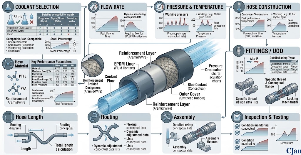
A practical design process can be organized into the following steps:
This process helps prevent individual component decisions from being made without considering the complete cooling system.
26. Hose Assembly Design for High-Density AI Servers
High-density AI servers can require many coolant connections within a limited physical space.
This makes compact routing and serviceability important design considerations.
A suitable hose assembly should provide enough flexibility to accommodate the installation while maintaining controlled geometry during operation.
The assembly should also be selected with the required coolant flow and pressure loss in mind.
For high-density server applications, see How to Choose the Right Liquid Cooling Hose for High-Density AI Servers.
27. Choosing a Hose Supplier for Custom Assemblies
When a standard hose is not sufficient, a hose supplier may need to provide a complete custom assembly.
Engineers should provide the supplier with clear application information rather than specifying only hose diameter.
Useful information includes:
- Coolant type
- Flow rate
- Pressure
- Temperature
- Hose dimensions
- Required length
- Fitting type
- UQD requirements
- Installation environment
- Testing requirements
This allows the manufacturer to evaluate the complete assembly rather than supplying a hose without sufficient application context.
28. CJAN Liquid Cooling Hose Assembly Solutions
CJAN provides liquid cooling hose solutions for applications where hose material, construction, fittings and routing requirements need to be considered together.
The CJAN Liquid Cooling application range covers flexible hose solutions for thermal-management systems.
Relevant hose products include LCH, LCH-SD and LCH-SDS.
For applications requiring a specific hose-and-connection configuration, the assembly should be developed according to the actual coolant, pressure, temperature, flow rate, routing and fitting requirements.
Conclusion
Reliable liquid cooling hose assemblies require more than selecting a suitable hose.
The hose, reinforcement, fittings, UQD connections, routing and assembly process all contribute to the performance of the finished connection.
For AI servers, the most practical approach is to start with the cooling system requirements and then work through material compatibility, hydraulic sizing, mechanical requirements, connection design and testing.
A well-designed hose assembly should provide the required coolant flow while remaining mechanically stable, serviceable and compatible with the operating environment.
In high-density AI cooling systems, treating the hose assembly as an engineered component rather than a simple accessory can make the overall cooling design easier to specify, install and maintain.
For more information, visit the CJAN Liquid Cooling application page.