GLOBAL
Liquid Cooling Hose Pressure Drop: How to Calculate and Control It in AI Data Centers
In an AI data center cooling system, the hose may look like a relatively simple component. From a hydraulic perspective, however, every hose adds resistance to coolant flow.
That resistance becomes important when multiple hoses, fittings, UQDs, manifolds and cold plates are connected into the same cooling loop.
If the pressure drop is higher than expected, the pump may need to operate at a higher pressure to maintain the required flow. In a densely populated AI rack, even relatively small pressure losses across individual components can become significant when they are repeated throughout the system.
This article explains the main factors affecting hose pressure drop and how engineers can evaluate them during AI server liquid cooling system design.
For the basic operating principle of AI data center liquid cooling, see How Does Liquid Cooling Work in AI Data Centers?.
1. What Is Pressure Drop in a Liquid Cooling Hose?
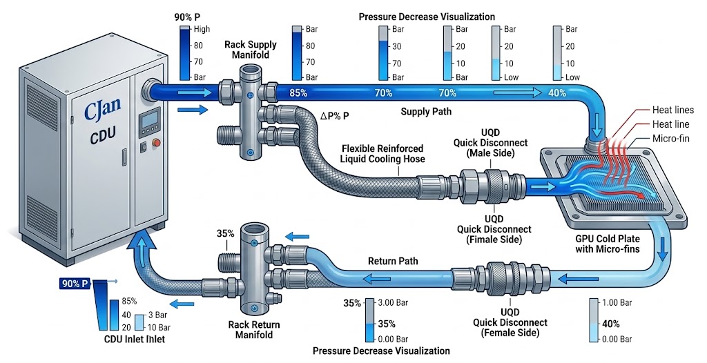
Pressure drop is the reduction in fluid pressure as coolant moves through a flow path.
In a liquid cooling hose, pressure is lost because the moving coolant experiences resistance from the hose wall and from changes in the flow path.
For a simplified cooling loop, the hydraulic path may look like this:
Every component in this path can contribute to the total pressure loss.
Therefore, hose pressure drop should be evaluated as part of the complete hydraulic system rather than as an isolated specification.
2. Why Pressure Drop Matters in AI Data Center Cooling
AI servers can require substantial coolant flow because of the thermal load generated by high-performance processors and accelerators.
As coolant flow increases, hydraulic resistance generally becomes more important.
The cooling system must provide sufficient flow to transport the required amount of heat away from the electronic components.
If excessive pressure loss exists in the circuit, the pump must provide additional pressure to maintain that flow.
This does not mean that the hose with the largest internal diameter is always the best choice. Hose diameter, system flow, available space, connection size and pressure-drop requirements must be considered together.
3. What Determines Liquid Cooling Hose Pressure Drop?
Several variables influence the pressure loss of a hose.
- Coolant flow rate
- Hose internal diameter
- Hose length
- Coolant viscosity
- Coolant density
- Internal surface characteristics
- Flow path geometry
- Bends and routing
- Connection design
Among these factors, flow rate, internal diameter and hose length are often particularly important when comparing hose configurations.
4. Flow Rate Has a Direct Impact
When more coolant needs to pass through the same hose, fluid velocity increases.
Higher velocity generally increases hydraulic resistance.
This is why a hose that performs adequately at a relatively low flow rate may create a substantially larger pressure drop when the cooling system operates at a higher flow rate.
| Flow Condition | Typical Hydraulic Effect |
|---|---|
| Lower flow | Lower coolant velocity and generally lower pressure loss |
| Design flow | Pressure drop should be checked against system requirements |
| Higher flow | Higher coolant velocity and generally higher pressure loss |
For this reason, manufacturers should ideally provide pressure-drop information at defined flow conditions rather than providing only a single nominal hose rating.
5. Why Hose Internal Diameter Matters
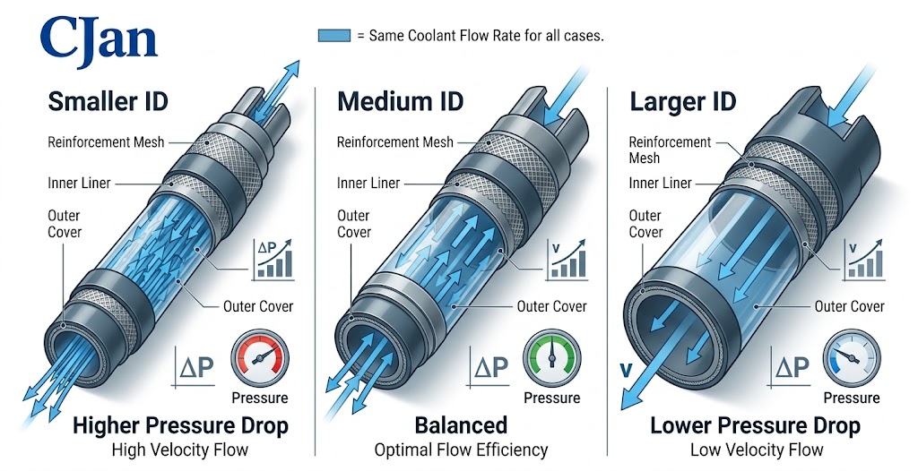
Internal diameter is one of the most important hose dimensions for hydraulic performance.
For the same coolant flow, a smaller internal passage results in higher fluid velocity.
A larger internal passage can reduce velocity and hydraulic resistance, although it may increase the physical size of the assembly.
This is especially important when the cooling loop uses relatively high flow rates.
6. Hose Length Also Contributes to Pressure Loss
Longer hose runs generally create more frictional resistance than shorter runs of the same hose construction and internal diameter.
In an AI rack, the difference may appear small for one hose. However, a system can contain multiple supply and return hoses.
The total hydraulic effect therefore needs to be considered across the complete circuit.
Hose length should be kept long enough for correct routing and maintenance access, but unnecessary excess length should be avoided.
7. Coolant Properties Affect Pressure Drop
Pressure drop cannot be evaluated accurately without knowing the coolant.
Different coolants can have different viscosity and density characteristics.
These properties influence the hydraulic behavior inside the hose.
For example, a water-based coolant and a coolant containing a higher concentration of glycol may behave differently even when they are flowing through the same hose at the same nominal flow rate.
8. Temperature Can Change Hydraulic Conditions
Coolant properties can change with temperature.
Because viscosity can vary with temperature, the pressure-drop behavior of a cooling loop may also change between operating conditions.
This is one reason why pressure-drop data should be interpreted together with the actual temperature range of the application.
9. Do Bends Increase Pressure Drop?
Yes. Changes in flow direction can contribute additional hydraulic resistance.
A hose routed with multiple bends may therefore have a different pressure-drop behavior from a straight hose of the same nominal length.
In practice, engineers should distinguish between:
- Friction loss along the hose length
- Additional resistance caused by bends
- Restriction caused by fittings
- Restriction caused by UQDs
Routing should also respect the hose's specified minimum bend radius.
For a broader discussion of hose routing and selection, see How to Choose the Right Liquid Cooling Hose for AI Servers.
10. UQDs Can Contribute to the Total Pressure Drop
In many serviceable liquid cooling systems, UQDs are used to simplify equipment connection and disconnection.
However, a UQD is part of the hydraulic path.
Its internal passage and flow geometry can contribute pressure loss.
This means that engineers should avoid evaluating the hose while ignoring the connection hardware.
When comparing different hose assemblies, the complete flow path provides a more useful engineering reference than the hose alone.
11. Hose Fittings Should Be Included in the Calculation
A hose assembly normally contains fittings or connection components at one or both ends.
The internal geometry of these components can create additional resistance.
A nominally large hose can therefore still have a relatively restrictive flow path if the connection components have a smaller internal passage.
When pressure drop is critical, engineers should examine the complete connection path from the hose ID through the fitting and UQD.
12. Pressure Drop and Pump Selection Are Connected
The pump must provide enough pressure to overcome the hydraulic resistance of the cooling circuit while maintaining the required flow rate.
A simplified relationship can be expressed as:
The actual pump selection process is more detailed and depends on the complete cooling architecture.
Nevertheless, minimizing unnecessary hydraulic resistance can make the overall system easier to manage.
13. Why a Larger Hose Is Not Always the Best Answer
It is tempting to solve pressure-drop concerns simply by increasing hose diameter.
That approach can work in some situations, but it is not always practical.
A larger hose can require:
- Larger fittings
- Larger UQDs
- More installation space
- Larger routing radius
- Different manifold ports
Therefore, the engineering objective is normally to find an appropriate balance between hydraulic performance and physical integration.
14. Pressure Drop Should Be Considered Alongside Bend Radius
A hose needs to fit into the available rack space without creating excessive bending or kinking.
A very tight routing configuration can alter the effective flow passage.
Therefore, pressure-drop evaluation should be performed on the intended installation configuration whenever possible.
The practical selection process should include both hydraulic and mechanical requirements.
15. Pressure Rating and Pressure Drop Are Different Specifications
These two specifications are sometimes confused.
Pressure rating describes the pressure that the hose is designed to withstand under specified conditions.
Pressure drop describes the pressure loss that occurs as coolant flows through the hose.
A hose can have a high pressure rating while still producing more pressure loss than desired at a particular flow rate.
16. How Engineers Can Compare Different Hose Sizes
When evaluating hose sizes, use the same operating conditions for each candidate.
A useful comparison should keep the following variables consistent:
- Coolant
- Coolant temperature
- Flow rate
- Hose length
- Connection configuration
The resulting pressure-drop data can then be compared more meaningfully.
| Parameter | Candidate A | Candidate B | Candidate C |
|---|---|---|---|
| Internal Diameter | Smaller | Medium | Larger |
| Flow Rate | Same test condition | ||
| Coolant | Same coolant | ||
| Hose Length | Same test length | ||
| Pressure Drop | Measure | Measure | Measure |
17. A Practical Pressure-Drop Evaluation Process
This approach reduces the risk of optimizing one component while creating an unintended restriction somewhere else in the cooling loop.
18. How Pressure Drop Relates to AI Rack Density
As AI computing systems become more densely integrated, cooling architecture can become more complex.
More processors, cold plates and connection points may require additional coolant paths.
That can increase the number of components contributing to total hydraulic resistance.
For high-density cooling systems, pressure-drop management therefore becomes an important part of system-level design.
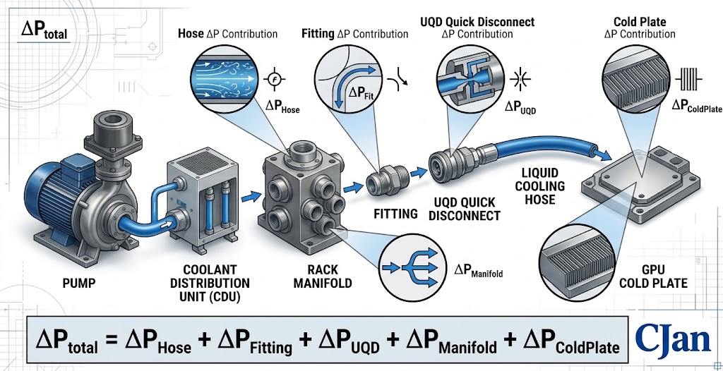
19. Pressure Drop Should Be Evaluated at the System Level
A hose supplier may provide pressure-drop information for a particular hose under specified test conditions.
That information is useful, but it does not represent the pressure loss of the entire cooling loop.
The system-level evaluation should include:
- CDU
- Manifold
- Supply hose
- UQDs
- Fittings
- Cold plate
- Return hose
- Other flow restrictions
This distinction is important when translating component data into an actual AI rack design.
20. What Data Should Be Requested From a Hose Supplier?
When pressure drop is an important design parameter, engineers should request enough information to reproduce or interpret the supplier's test conditions.
Useful information includes:
- Hose internal diameter
- Test length
- Coolant used for testing
- Coolant temperature
- Flow rate
- Pressure-drop result
- Connection configuration
Without the test conditions, a pressure-drop number may be difficult to apply directly to another cooling system.
21. CJAN Liquid Cooling Hose Options
CJAN provides several liquid cooling hose configurations that can be evaluated according to system requirements.
The current CJAN LCH Liquid Cooling Hose is designed for liquid cooling applications where engineers need to consider hydraulic, thermal and mechanical requirements together.
Other configurations include CJAN LCH-SD and CJAN LCH-SDS.
Product selection should be based on the actual coolant, pressure, temperature, flow rate, dimensions and connection requirements.
22. Connecting Pressure-Drop Analysis With Hose Selection
Pressure drop should not be treated as an isolated calculation performed after the hose has already been selected.
It should be included during the initial hose selection process.
The broader selection framework is covered in How to Choose the Right Liquid Cooling Hose for AI Servers.
That process considers coolant compatibility, flow, pressure, temperature, hose dimensions, bend radius, mechanical environment and UQD requirements together.
23. Pressure Drop in a Real Liquid Cooling Hose Assembly
The finished hose assembly can behave differently from a simple straight length of hose.
For example, a typical assembly may include:
Each section can influence the final hydraulic result.
For this reason, prototype or assembly-level testing can be valuable when the cooling system has tight hydraulic requirements.
24. Five Common Mistakes in Pressure-Drop Evaluation
Mistake 1: Looking Only at Hose Diameter
Diameter matters, but it does not describe the entire hydraulic path.
Mistake 2: Ignoring Flow Rate
Pressure-drop data without a defined flow condition is difficult to interpret.
Mistake 3: Ignoring UQDs
UQDs are part of the flow path and can contribute additional resistance.
Mistake 4: Ignoring Coolant Temperature
Coolant properties can vary with temperature, affecting hydraulic behavior.
Mistake 5: Evaluating Only a Straight Hose
The final installation may contain bends, fittings and connection components that change the actual pressure loss.
25. A Simple Design Checklist
| Question | Check |
|---|---|
| What coolant is being used? | Confirm formulation and temperature |
| What flow rate is required? | Define target and operating range |
| What is the hose ID? | Check against hydraulic requirements |
| How long is the hose? | Include actual routing length |
| What fittings are used? | Check internal flow path |
| What UQD is used? | Check flow restriction |
| What is the total pressure drop? | Evaluate the complete loop |
| Is the pump operating point suitable? | Confirm required flow and pressure |
Conclusion
Liquid cooling hose pressure drop is a system-level consideration in AI data center cooling.
Flow rate, hose internal diameter, hose length, coolant properties, temperature, bends, fittings and UQDs can all influence the hydraulic resistance of the cooling circuit.
The most useful approach is therefore to evaluate the complete coolant path rather than selecting a hose based only on pressure rating or nominal size.
For AI server cooling projects, CJAN provides LCH, LCH-SD and LCH-SDS liquid cooling hose configurations that can be evaluated against specific application requirements.
When requesting a hose recommendation, providing the coolant, flow rate, pressure, temperature, hose dimensions and connection configuration gives the supplier a much stronger basis for engineering evaluation.
For more information, visit the CJAN Liquid Cooling Solutions page or review the CJAN LCH Liquid Cooling Hose.