
BLOG
2026/08/17Clicks:410
In a direct liquid cooling system, the CDU is not the final destination for the coolant.
The coolant must move from the Coolant Distribution Unit (CDU) to the rack, manifold, and eventually the cold plates serving the GPUs or other high-power components.
This makes the connection between the CDU and rack an important part of the cooling architecture.
A typical path may look like:
CDU
↓
Supply Header
↓
Flexible Hose Assembly
↓
Rack Manifold
↓
Distribution Hose
↓
Cold Plate
↓
Return Hose
↓
CDU
The hose assembly therefore has to do more than simply transport coolant.
It must accommodate:
For high-density AI infrastructure, these details can determine whether a cooling loop remains reliable over years of operation.
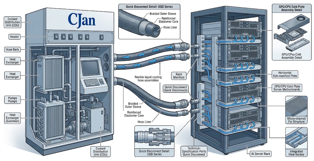
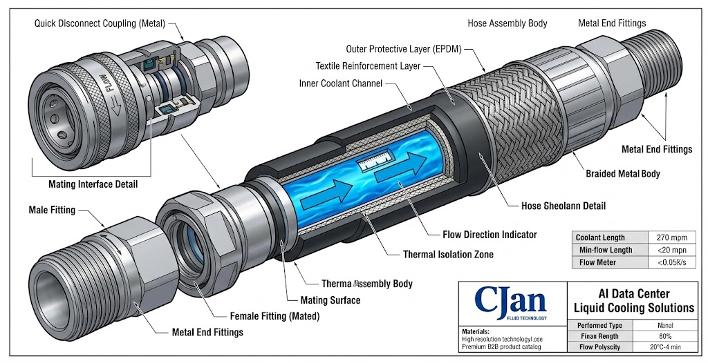
A CDU-to-rack hose assembly is a preconfigured fluid connection used to transport coolant between a CDU and the cooling distribution point at an AI rack.
A typical assembly may include:
Liquid Cooling HoseDepending on the architecture, the assembly may connect directly to a rack manifold or to another cooling distribution component.
The important point is that the hose, fitting and coupling should be treated as one engineered assembly, rather than as independent components.
The main cooling equipment may receive most of the attention during system design.
However, connection points can become critical failure locations.
Potential problems include:
A well-designed hose assembly helps avoid these issues before the system reaches operation.
Before selecting a hose, define the complete coolant path.
For example:
CDUThe hose requirements will depend on where it is installed.
A CDU-to-rack hose may have different requirements from a short hose connecting a cold plate to a manifold.
Flow is one of the first parameters engineers should establish.
A hose that is too small can create excessive pressure loss.
A larger hose may reduce resistance, but it also requires:
Therefore, hose diameter should be selected according to the actual cooling loop.
A simple design sequence is:
Rack Heat LoadThis is more reliable than selecting hose size simply because it matches an existing connector.
The coolant determines which materials should be considered.
For many water-based data center cooling systems, EPDM is a practical option because of its combination of flexibility and coolant compatibility.
Other applications may require:
The selection should consider:
CJAN's current product portfolio includes dedicated liquid cooling hose products, including LCH, LCH-SD and LCH-SDS solutions. The company's website identifies LCH as a hose developed for data-center liquid cooling, while the LCH-SD and LCH-SDS products are specifically positioned for fire-resistant data-center liquid cooling applications.
A common mistake is to make the hose as short as possible.
Shorter does not always mean better.
A hose that is too short can create:
On the other hand, excessive hose length can create:
The goal is to provide enough length for natural routing and maintenance movement without creating unnecessary hose.
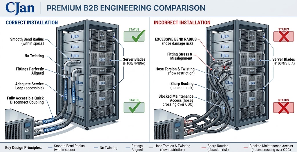
The hose should follow a smooth route from the CDU to the rack.
Avoid forcing the assembly into a tight bend immediately next to the fitting.
A better arrangement is:
 Rather than:
The second configuration can place excessive mechanical stress near the connection.
The manufacturer's specified minimum bend radius should always be followed.
Bending and twisting are not the same.
A hose may appear correctly routed while still being installed under torsional stress.
This can occur when:
During installation, the assembly should be positioned naturally before the final connection is secured.
A CDU hose assembly is only as reliable as its weakest connection.
Fitting selection should consider:
Potential connection options include:
For serviceable AI racks, quick disconnects can be particularly useful because they allow faster equipment isolation and replacement.
A typical service connection can be arranged as:
CDUThe UQD becomes a defined service interface.
This can simplify:
However, the UQD should be sized according to the required flow and pressure rather than selected solely by nominal hose diameter.
Pressure loss occurs throughout the cooling loop.
The hose contributes to total system pressure drop along with:
A useful engineering concept is:
Total Pressure Drop = Hose + Fittings + UQD + Manifold + Cold PlateThis is why evaluating the hose alone is insufficient.
A hose with a large internal diameter can still be part of a high-resistance system if the selected UQD or fitting has a restrictive internal passage.
For high-density AI cooling, a preassembled hose solution can simplify deployment.
A typical assembly may be:
[UQD]────[Fitting]══ LIQUID COOLING HOSE ══[Fitting]────[UQD]The supplier can control:
This can reduce variability between individual installations.
The hose assembly must be compatible with the actual cooling system pressure.
Engineers should identify:
Do not use burst pressure as the normal operating pressure.
The complete assembly should be evaluated, including:
hose + fitting + coupling + assembly method.
The hose material should be evaluated against the actual coolant rather than a generic "water cooling" specification.
Consider:
This is especially important when moving between different coolant formulations.
Leakage prevention should begin at the design stage.
Potential leakage points include:
A reliable design therefore combines:
Compatible material + correct fitting + controlled assembly + testing
rather than relying on any single component.
The hose should not prevent technicians from accessing:
Avoid routing hoses directly across removable equipment.
A useful principle is:
The cooling connection should remain accessible after the rack is fully assembled.
This becomes increasingly important as AI rack density increases.
Before installing a hose assembly into an operating AI rack, appropriate testing should be completed according to the system specification.
Possible checks include:
Verify:
Verify assembly integrity.
Inspect:
Confirm that the assembly does not introduce unexpected flow restriction.
The required flow rate should drive the hydraulic design.
This can create unnecessary stress at fittings.
A restrictive coupling can become a significant resistance point.
The hose should not be twisted to compensate for poor alignment.
The connection should remain accessible after rack installation.
The final performance belongs to the assembly, not just the hose.
| Parameter | What to Confirm |
|---|---|
| Coolant | Material compatibility |
| Flow rate | Required rack cooling flow |
| Hose ID | Hydraulic requirement |
| Working pressure | System operating condition |
| Temperature | Normal and maximum |
| Bend radius | Installation requirement |
| Hose length | Routing and service access |
| Fittings | Mechanical and fluid compatibility |
| UQD | Flow, pressure and leakage performance |
| Assembly | Crimping / connection quality |
| Testing | Pressure and leakage verification |
| Maintenance | Accessibility after installation |
CJAN's liquid cooling portfolio currently includes dedicated products for data center cooling, including the LCH, LCH-SD, and LCH-SDS families. The company also lists a CJFLEX HAT high-airtightness hose for IDC liquid cooling applications.
For a CDU-to-rack application, the appropriate product should be selected according to the actual:
Rather than treating one hose model as a universal solution.
The LCH product is positioned by CJAN as a liquid cooling hose developed for data-center liquid cooling systems.
Recommended application direction:
CJAN currently describes the LCH-SD as a fire-resistant hose for data center liquid cooling systems.
Recommended application direction:
The LCH-SDS is positioned as an ultra-flexible fire-resistant EPDM hose for data center liquid cooling systems.
Recommended application direction:
For an actual project, the final hose model should be matched to the customer's operating parameters rather than selected from the product name alone.
The CDU-to-rack connection is more than a simple hose connection.
It is a hydraulic, mechanical and maintenance interface within the AI cooling system.
A reliable design should simultaneously consider:
For AI data centers, the most effective approach is to design the complete hose assembly rather than selecting the hose independently from its fittings and couplings.
CJAN's current liquid cooling portfolio provides several hose options for data center applications, including LCH, LCH-SD and LCH-SDS, allowing the final configuration to be matched to the project's actual operating conditions.
Quick Disconnect Couplings for Liquid Cooling Systems: Benefits, Selection and Best Practices
 Mobile


 GLOBAL


