
BLOG
2026/08/07Clicks:368
The rapid development of artificial intelligence is pushing data centers toward higher levels of computing density.
Modern AI servers equipped with high-performance GPUs generate significantly more heat than traditional computing equipment. To maintain stable operating temperatures, many next-generation data centers are adopting direct liquid cooling systems.
However, a liquid cooling system is not simply about adding coolant around the heat source.
The system must deliver the correct amount of coolant at the correct flow rate.
If coolant flow is too low:
If coolant flow is unnecessarily high:
Therefore, understanding coolant flow requirements is essential when designing reliable AI cooling infrastructure.
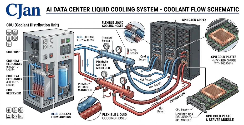
In a liquid cooling system, coolant performs one primary function:
Transport heat away from high-power components.
The cooling process follows:
GPU / CPU Heat Generation

↓

Cold Plate Heat Transfer

↓

Coolant Absorbs Heat

↓

Cooling Hose Transfers Heated Coolant

↓

CDU Removes Heat

↓

Coolant Returns to Server
The efficiency of this process depends on:
Coolant flow rate refers to the amount of liquid passing through the cooling loop over a specific period.
It is commonly expressed as:
The required flow rate depends on:
Higher heat loads generally require greater coolant circulation capability.
The basic relationship is:
Heat Removed =
Coolant Flow × Specific Heat × Temperature Difference
In practical terms:
Higher GPU power:
↓
More heat generation:
↓
Higher cooling requirement:
↓
Higher coolant flow demand
This is why AI data centers require carefully designed cooling loops.
A typical AI cooling system contains multiple cooling paths.
For example:
CDU

↓

Rack Manifold

↓

Multiple GPU Servers

↓

Cold Plates

↓

Return Loop
Each branch must receive appropriate coolant flow.
Poor flow balance can cause:
Proper flow management improves:
Although hoses are not active cooling devices, they directly influence flow performance.
Important hose factors include:
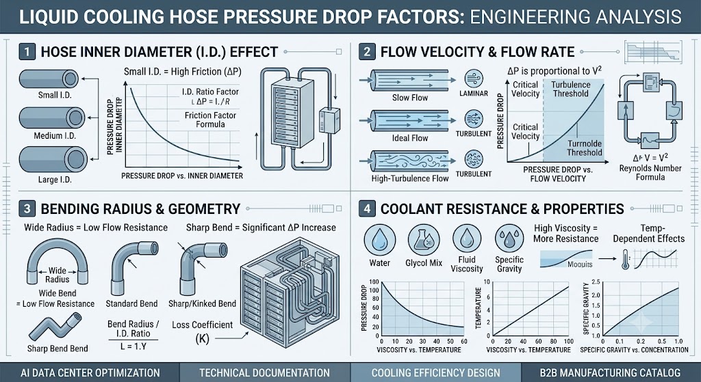
The internal diameter affects:
A smaller diameter may increase pressure drop.
A larger diameter may increase system size and cost.
The correct size depends on the overall cooling design.
Pressure drop occurs when coolant loses energy while flowing through the system.
Factors affecting pressure drop include:
Excessive pressure drop can increase pump workload.
Installation layout affects flow performance.
Sharp bends or improper routing may:
Flexible cooling hoses allow engineers to optimize routing while maintaining reliable connections.
Hose size selection should consider:
Determine the coolant volume required by the cooling system.
Evaluate:
Consider:
A practical hose design should allow:
The CDU controls coolant circulation throughout the system.
It manages:
The hose connecting the CDU to server cooling components must support the required flow conditions.
A poorly selected hose may limit system performance even when the CDU is correctly designed.
A matching connector size does not always mean optimal flow performance.
A hose may physically fit but create unnecessary resistance.
Longer hose paths increase:
AI infrastructure evolves quickly.
Cooling designs should consider future rack density increases.
CJAN LCH series cooling hoses are designed for applications requiring:
Applications include:
Product options:
Suitable for general liquid cooling applications.
Features:
Designed for applications requiring enhanced safety considerations.
Suitable for:
Designed for:
Coolant flow management is a fundamental part of AI data center liquid cooling design.
A successful cooling system requires the right balance between:
The liquid cooling hose plays an important role by maintaining stable coolant transportation between cooling components.
As AI computing power continues to increase, precise coolant flow management will become increasingly important for maintaining efficient and reliable data center operation.
 Mobile


 GLOBAL


