GLOBAL
How to Select Liquid Cooling Hose Size: Flow Rate, Pressure Drop and Rack Cooling Requirements
Introduction
When engineers select a liquid cooling hose for an AI server rack, the first question is often:
What hose diameter should I use?
It sounds simple. In practice, hose diameter is determined by several variables:
- Rack heat load
- Required coolant flow
- Coolant properties
- Temperature difference
- Hose length
- Internal diameter
- Fittings
- Quick disconnects
- Allowable pressure drop
A hose that physically fits a connector may still be the wrong hydraulic size. For AI data center cooling, the better approach is to start with the cooling requirement and work backward toward the hose specification.
1. Start With Rack Heat Load
The cooling system exists to remove heat. Therefore, hose sizing should ultimately relate to the heat generated by the equipment.
A simplified relationship is:
In practical engineering terms:
↓
Required Heat Removal
↓
Coolant Flow Rate
↓
Hose Internal Diameter
↓
Pressure Drop
↓
CDU Pump Requirement
This sequence is much more useful than starting with the hose connection.
2. Why AI Rack Power Matters
Traditional data center racks may have relatively moderate thermal loads. AI racks are different. High-performance GPU systems can create substantially higher heat density, making liquid cooling attractive because coolant can transport heat much more effectively near the heat source.
As rack power increases, the cooling system may require:
- Higher coolant flow
- Larger flow passages
- Lower hydraulic resistance
- More efficient cold plates
- Higher-capacity CDUs
The hose is only one part of this hydraulic network, but its internal diameter directly affects flow resistance.
3. Internal Diameter Matters More Than Nominal Connection Size
This is one of the most important points in hose selection. A connector may be described as:
- 3/4 inch
- 1 inch
- 1-1/4 inch
But that does not necessarily tell you the actual flow capacity of the complete hose assembly. The engineer should check:
For example:
│
│ 1" connection
▼
Fitting
│
▼
Hose ID
│
▼
UQD internal passage
│
▼
Manifold
If one component has a substantially smaller internal passage, it can become a hydraulic restriction.
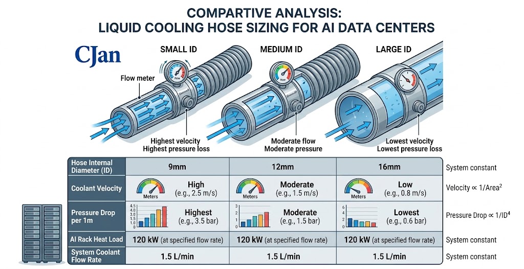
4. Coolant Flow Rate Is a Primary Sizing Parameter
The required flow rate depends on:
- Heat load
- Coolant type
- Supply temperature
- Return temperature
- Desired temperature rise
For a simplified water‑based cooling calculation:
Where:
Q = coolant mass flow rate
P = heat load
Cp = specific heat capacity
ΔT = allowable coolant temperature rise
The exact calculation should use the actual coolant properties and engineering units specified by the system designer.
5. A Simple Example
Suppose an AI cooling loop must remove 100 kW of heat and the design allows a coolant temperature rise of 10°C. For water‑based cooling, the required flow is roughly on the order of:
The example demonstrates an important principle: High rack heat load can require substantial coolant flow, which directly influences hose diameter.
6. Hose Diameter and Pressure Drop
Increasing hose diameter generally reduces flow resistance. Reducing diameter generally increases flow velocity and pressure loss.
A simplified relationship is:
↓
Higher Flow Velocity
↓
Higher Pressure Loss
while:
↓
Lower Flow Velocity
↓
Lower Pressure Loss
However, simply choosing the largest available hose is not necessarily the best solution. Larger hoses can introduce:
- Higher material cost
- Larger fittings
- Greater bending requirements
- More installation space
- Increased coolant volume
The objective is appropriate sizing, not maximum sizing.
7. Hose Length Also Affects Pressure Drop
Two hoses with the same internal diameter can have different hydraulic performance if their lengths differ.
5 m hose → Higher friction loss
This becomes important when a CDU is positioned far from the rack. Long routing may increase:
- Pressure loss
- Coolant volume
- Installation complexity
Therefore, hose length should be included in the hydraulic calculation.
8. Don't Forget the Fittings
The hose is not the only source of pressure loss. A complete cooling assembly may contain:
- Hose
- Elbows
- Adapters
- Quick disconnects
- Valves
- Manifolds
The system pressure loss can therefore be considered conceptually as:
This is particularly important in high‑flow AI cooling systems.
9. Quick Disconnects Can Become a Restriction
Quick disconnect couplings are extremely useful for rack maintenance. However, engineers should not assume that all UQDs have the same hydraulic performance.
Two couplings with the same nominal connection size may have different:
- Internal flow passages
- Pressure drop
- Valve structures
- Flow coefficients
Therefore, when specifying a liquid cooling assembly, request the UQD's hydraulic performance data where available.
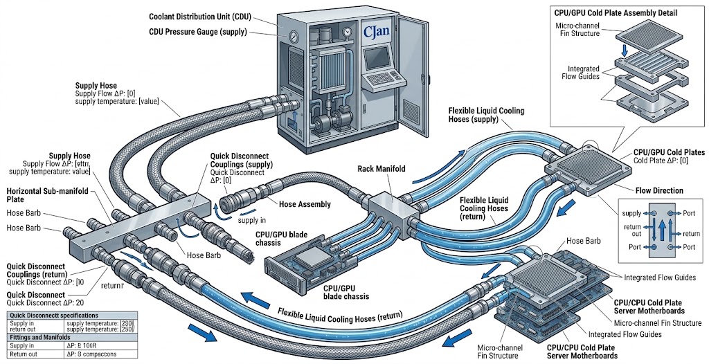
10. Hose Diameter Selection Should Follow the Cooling Architecture
A typical AI cooling system might look like:
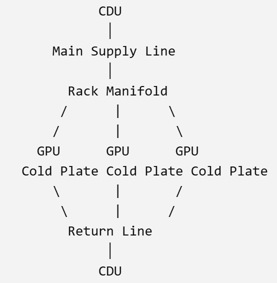
The required hose size may therefore differ at different points.
| Location | Typical Design Consideration |
|---|---|
| CDU → Rack | Higher flow, longer routing |
| Rack → Manifold | Flow distribution |
| Manifold → Cold Plate | Branch flow |
| Cold Plate → Manifold | Return flow |
| Manifold → CDU | Combined return flow |
There is no reason to assume that every hose in the system must have the same diameter.
11. Supply and Return Hoses
Supply and return hoses normally carry similar total system flow at the corresponding point in the loop. However, their operating conditions may differ slightly depending on architecture.
Engineers should consider:
- Supply temperature
- Return temperature
- Pressure
- Flow
- Hose routing
Both should be specified as part of the complete cooling loop.
12. Avoid Selecting Hose Size From Existing Hardware Alone
A common situation is:
“The CDU has a 1‑inch port, so we need a 1‑inch hose.”
That can be a reasonable starting point—but it is not a complete engineering specification. The actual requirement may be influenced by:
- Port geometry
- Fitting internal diameter
- UQD passage
- Hose ID
- Required flow
- Pressure drop
The correct question is:
13. Consider the Hose Bend Radius
Hydraulic sizing is not the only concern. A hose may have the correct ID but still be unsuitable if it cannot be routed properly.
A tight bend can:
- Restrict flow
- Increase mechanical stress
- Reduce hose service life
- Place stress on fittings
Therefore:
14. Flexible Hoses Need Installation Space
AI racks are becoming increasingly dense. Space is occupied by:
- Power distribution
- Network cables
- Cooling manifolds
- Server hardware
- Monitoring equipment
The selected hose diameter should therefore balance hydraulic requirements against installation space. This is one area where highly flexible hose constructions can provide a practical advantage.
15. How to Select a Hose Size: Practical Workflow
For an AI liquid cooling project, the following workflow is useful.
| Step | Action |
|---|---|
| 1 | Determine heat load – Example: Rack = 100 kW |
| 2 | Determine coolant – Example: Water‑based coolant |
| 3 | Determine allowable ΔT – Example: 10°C |
| 4 | Calculate required flow – Use actual coolant properties |
| 5 | Establish allowable pressure drop – Based on CDU/pump capability |
| 6 | Evaluate hose ID – Compare candidate diameters |
| 7 | Add fittings and UQDs – Calculate complete assembly pressure loss |
| 8 | Check mechanical installation – Verify bend radius, length, routing, connection orientation |
| 9 | Confirm safety margin – Check pressure rating, temperature rating, material compatibility, assembly performance |
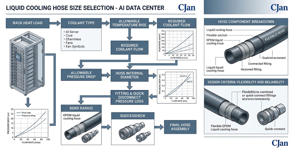
16. Example Hose Selection Matrix
The following is a design framework rather than a universal sizing table.
| Cooling Requirement | Initial Design Direction |
|---|---|
| Low rack heat load | Smaller flexible hose may be sufficient |
| Medium rack heat load | Medium ID with controlled pressure drop |
| High rack heat load | Larger ID / low‑resistance assembly |
| Long CDU‑to‑rack route | Pay particular attention to pressure loss |
| Compact rack | Prioritize flexibility and bend radius |
| High flow | Evaluate hose + UQD + fitting as a system |
| High‑purity coolant | Evaluate fluoropolymer options |
| Fire‑resistance requirement | Consider dedicated fire‑resistant hose constructions |
17. Material and Size Must Be Selected Together
Hose size cannot be separated completely from hose construction.
| Material | Considerations |
|---|---|
| EPDM | Often attractive for water‑based cooling, flexible rack connections, general data center cooling |
| Silicone | Can be considered where flexibility is important and temperature performance is demanding |
| PTFE / PFA | More appropriate for applications where chemical resistance, high purity, or specialized coolant compatibility are important |
18. CJAN Liquid Cooling Hose Options
CJAN's current website identifies Liquid Cooling Hose / LCH as a dedicated product for liquid cooling systems in data centers.
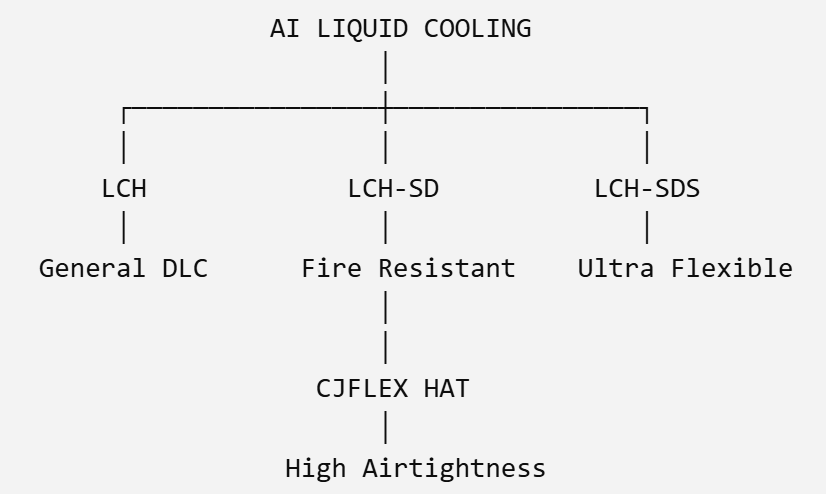
The current product portfolio also includes:
- LCH – For general liquid cooling applications
- LCH‑SD – Fire‑resistant EPDM hose for data center liquid cooling applications
- LCH‑SDS – Ultra‑flexible fire‑resistant EPDM hose for data center liquid cooling applications
- CJFLEX HAT – High‑airtightness hose for IDC liquid cooling systems
Product architecture overview:
The final model should still be selected against the customer's actual flow, pressure, temperature, coolant and installation requirements.
19. Questions to Send to a Hose Supplier
When requesting a quotation, engineers should provide more than: “Please quote a 1‑inch liquid cooling hose.”
A better RFQ includes:
Coolant: __________
Operating Temperature: __________
Maximum Temperature: __________
Operating Pressure: __________
Required Flow: __________
Hose ID / Connection: __________
Required Length: __________
Bend Radius: __________
Fitting Type: __________
Quick Disconnect: Yes / No
Fire Resistance: Required / Not Required
Quantity: __________
This information allows the supplier to recommend a realistic configuration instead of simply matching a nominal diameter.
Common Hose Sizing Mistakes
| # | Mistake | Consequence |
|---|---|---|
| 1 | Matching Hose Diameter to Port Size | A matching port does not guarantee adequate hydraulic performance. |
| 2 | Ignoring Pressure Drop | The pump may have sufficient flow capacity but insufficient pressure margin. |
| 3 | Ignoring UQD Restrictions | A restrictive UQD can offset the benefit of a larger hose. |
| 4 | Making the Hose Too Long | Longer routes increase pressure loss and installation complexity. |
| 5 | Choosing the Largest Hose Available | Oversizing can create unnecessary cost and installation problems. |
| 6 | Ignoring Bend Radius | Hydraulic performance and mechanical installation must be evaluated together. |
Conclusion
Liquid cooling hose sizing should never be reduced to a single question such as:
"What size is the CDU port?"
A reliable selection starts with the cooling requirement and works through the complete hydraulic and mechanical system:
For AI data centers, this approach becomes increasingly important as rack power density increases.
CJAN's current liquid cooling portfolio includes LCH, LCH-SD, LCH-SDS and CJFLEX HAT, allowing different hose constructions to be considered according to the project's requirements.
The key principle is simple: